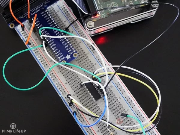

A voltage divider connected to 5V on the Raspberry Pi.An analog light sensor (light variable resistor).We are going to show you how to read these four sensors: What is the O2 Level by reading the analog O2 sensor? The Four Parts to this Tutorial Part 1 - Overview of the ADC Raspberry Pi Project Part 2 - Hooking up the Hardware Part 3 - The ADC Raspberry Pi Project Software Part 4 - Two Really Cool Experiments with the ADC Raspberry Pi In This Tutorial What is the supply voltage on my Raspberry Pi? There are many different reasons to read analog signals. In this Tutorial, you will learn how use an 4 Channel 16 bit Analog to Digital Converter (ADC) on your Raspberry Pi.

Have you ever wanted to read analog (voltage level) levels and sensors on your Raspberry Pi? While you can read digital sensors with the Raspberry Pi, there is no built in analog to digital converter on your Raspberry Pi. Why is it 100 or where is pin 100?īy the way, I tried to compile and run the gertboard.c example with "gcc -Wall -o gertboard gertboard.Tutorial – Using an Analog to Digital Converter with your Raspberry Piĭid you ever want to read a voltage (rather than a 1 or 0) on your Raspberry Pi? You can do this with an Analog to Digital Converter. One more thing I would like to ask, I don't get the pinbase explanation. I followed your tutorial on placing the 5 jumper pins on the SPI. Do I jump the wires in the same way as the example? However in my case I only need the Analog to Digital converter. Problem is I'm unsure where to place the jumper wires in order to get it to work. I realised that what I wanted to do is Analogue to Digital, not Digital to Analogue. I have also found the gertboard.c example in the wiringpi folder on my RPI. Yes I have been looking around your website and stumbled across this link. Then you can look at the examples and use the analogRead() and analogWrite() functions that wiringPi supports. Get that here: and follow the download link.

What you need to do is look at the Gertboard examples in the wiringPi source code. I am following this example: Gertboard Analog In/OutĪlso, what is the jumper wiring set up for my case? I only need to connect GPIO18 to DA1/DA0? I can just do a pwmwrite to the the analogue pin? Or do i still have to use AnalogWrite function? The next step for me is doing a digital to analogue conversion and outputting it on the GertBoard's DAC Pin.

My Android phone is able to control the pwm voltage output of the pi. I am using wiringPi to do the coding in C.


 0 kommentar(er)
